ADJUSTMENTS ON
LINOTYPE MODELS
29, 30, 33, 34, 35, and 36
EQUIPPED WITH THE ELECTROMATIC SAFETY
Sales-Service
Mergenthaler Linotype Company
Brooklyn 5, N.Y.
September 1953, Service Instruction No. 16
This Service Instruction pertains to the maintenance and adjustment of the following mechanisms on Models 29, 30, 33, 34, 35 and 36 Linotypes which are equipped with the Electromatic Safeties:
Swinging Keyboard Rod (Long) Frame (72/90)
(For Models 29, 30, 35 and 36)
Hand Operated Mixer Shift.
(For Models 29, 30, 35 and 36)
Oscillating Front.
(For Models 29, 30, 35 and 36)
Magazine Frame. (For all models)
Channel Entrance.
(For Models 33, 34, 35 and 36)
Distributor Boxes.
The content of these instructions is not intended to cover all the adjustments pertinent to these mechanisms but only those which may not be generally known in the field and which are vital to the proper operation of the Linotype. For more general information regarding maintenance and adjustments of the mechanisms, the reader is referred to the Linotype publication "Linotype Machine Principles", which can be ordered from the Mergenthaler Linotype Company.
-2-
SWINGING KEYBOARD ROD (LONG) FRAME
The following material pertains to Mixer Models 29, 30, 35 and 36.
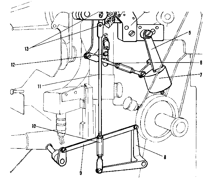
The keyboard rod (long) frame on the 72/90 Mixer Linotype pivots at the top. Its lower end swings by means of two linkages which connect the lower end of the frame to a shaft which partially rotates so that either the 72 or 90 set of keyboard rods may be brought into operating position over the short keyboard rods.
The hinge pin brackets (12 fig. 1), on which the keyboard rod frame hinges, are vertically adjustable so that the proper clearance between the short and long keyboard rods can be maintained.
Alignment of Keyboard Rods
The keyboard rod (long) guide (lower) is provided with elongated screw holes so that the long keyboard rods can be properly aligned, from left to right, with the short keyboard rods.
A turnbuckle (10) at the lower end of rod (11) provides an adjustment to properly locate the frame so that the lower ends of the long keyboard rods will be properly positioned over the short keyboard rods.
The l.h. keyboard rod frame connecting link is fastened to the frame with an adjustable eccentric shoulder screw. By use of this adjustment screw the keyboard rods can be aligned parallel to the short keyboard rods.
Removal of Keyboard Rod (Long) Frame
The keyboard (long) frame is removed from the Model 35 and 36 by first removing the face plate and associated parts, the spaceband lever keyrod pin, and disconnecting the two links which control the swinging motion. Then remove the two wing pins which serve as hinge pins.
-3-
It is not necessary to remove the entire face plate in order to remove the keyboard (long) frame from the Model 29 and 30. First remove the keyboard, the front cover, the spaceband lever keyrod pin and disconnect the two links which control the swinging motion. Then remove the wing pins which serve as hinge pins.
HAND OPERATED MIXER SHIFT
The linkage (8 & 9, Fig. 1) by means of the shift handle, actuates the rod (11), thereby controlling the position of the oscillating assembler front. This linkage also serves to position the swinging keyboard rod frame on 72/90 mixers
The counterbalance weight (7) in conjunction with linkage (5 & 6) counterbalances the weight of the oscillating assembler front in order to make hand shifting easier.
-4-

Fig. 1 Oscillating Assembler Front Retaining Mechanism and Linkage.
-5-
OSCILLATING ASSEMBLER FRONT ADJUSTMENTS
Oscillating Assembler Front Stop Screw Adjustments
The upper stop screw (l Fig. 1) provides an adjustment to obtain the proper relationship between the oscillating assembler front (20 Fig. 2) and the pivoting front guide holder (16 Fig. 2) when the oscillating front is in the upper position as shown in Fig. 2.
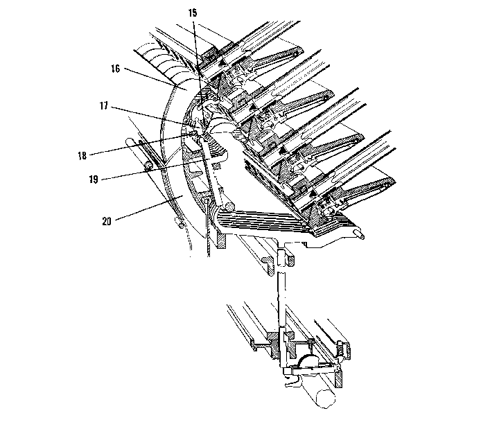
Fig. 2 Section through Main Magazines of Escapement, Oscillating Front and Keyboard Rods in position to release matrices from top magazine.
-6-
Proper adjustment of the upper stop screw (1 Fig. 1) locates the oscillating assembler front in a position which permits the push rods (19 Fig. 2) in the oscillating front to properly contact the tappets (17 Fig. 2) in the pivoting front guide holder. Caution-Improper adjustment of the upper stop screw will cause the push rods (19 Fig. 2) in the oscillating front to bind on the pivoting front at (15 or 18 Fig. 2) and will result in faulty matrix response.
The lower stop screw is adjusted to permit a slight clearance between the oscillating front (22 Fig 3) and the extension holder (21) when the oscillating front is in the lower position as shown in (Fig 3).
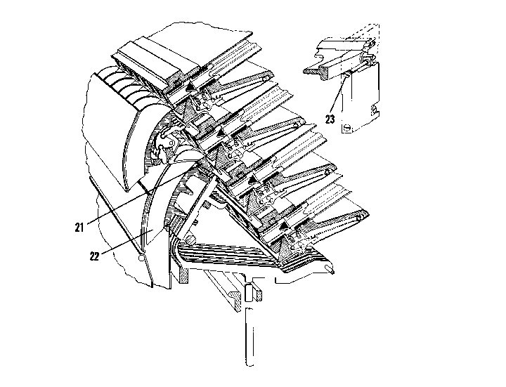
Fig. 3 Section through Main Magazines of Escapement, Oscillating Front and Keyboard Rods in position to release matrices from second magazine.
-7-
If the stop screw adjustments are changed., it will be necessary to readjust the latch pawl screw adjustments of the retaining mechanism proportionately. These adjustments are explained in a subsequent paragraph under the heading "Retaining Mechanism Adjustments".
Oscillating Assembler Front Retaining Mechanism
The retaining mechanism of which (2, 3, 4, 13 Fig. 1) are the principle parts serves to retain or lock the oscillating assembler front and the swinging keyboard rod frame in either operating position.
The final movement of the mixer shift handle at the completion of the shift in either direction, actuates the retaining mechanism to lock the oscillating front in operating position. The initial movement of the shift handle at the start of the shift reverses the action of the retaining mechanism to unlock the oscillating front.
Oscillating Assembler Front Retaining Mechanism Adjustments
The latch pawl screws (13 Fig. 1) are adjusted for a minimum clearance between the heads of the latch pawl screws and the steel projection at the end of the connecting lever (14). At this time the oscillating assembler front should be in operating position with the connecting lever against either the upper or lower stop screw. This slight clearance prevents latch pawl screws (13) from binding on the connecting lever projection and interfering with the movement of the latch pawl (2) when the locking or unlocking function takes place. Proper adjustment of the latch pawl screws permits just enough freedom between the points mentioned to insure the proper action of latch pawl (2). Excess clearance between these points will prevent the oscillating assembler front from being held in proper operating position.
-8-
Removal of Escapement Verge Plunger Tappet (Lower)
Push Rods and Holder Assembled
The Escapement Verge Plunger Tappet (Lower) Push Rods (52 Fig. 4) on Mixer Models 29, 30, 35 and 36 should be removed and cleaned when necessary. These push rods and holder can be removed as a unit in a few minutes by proceeding as follows:
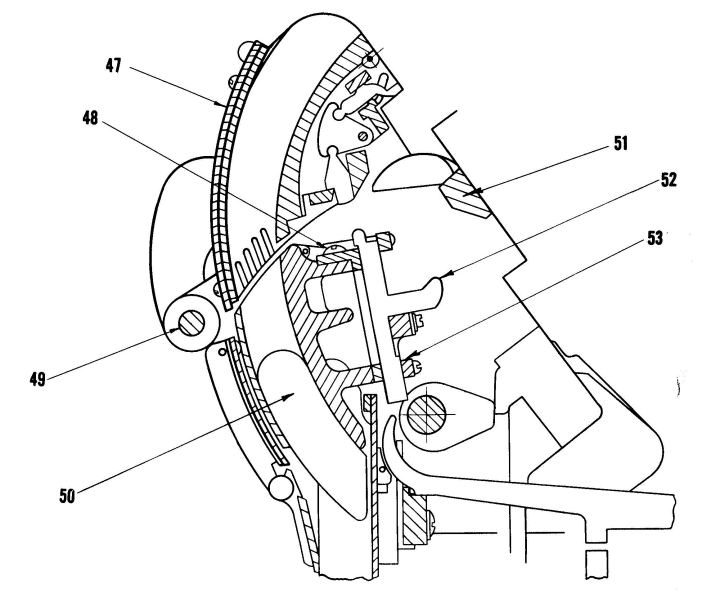
Fig. 4 Section through Pivoting Front and Oscillating Front showing the Escapement Verge Plunger Tappet (Lower) Push Rods and Holder Assembled
-9-
Have the Oscillating Front (50) in the position to release matrices from the top magazine.
Elevate magazines to uppermost position.
Remove Pivoting Front (47) by sliding out shaft (49).
Scribe a mark at the ends of the assembling guide (Intermediate) extension (51) to assist in aligning it properly when replacing it, and remove it by taking out the fastening screws.
Remove the lower push rod retaining strip (53)
Remove the Escapement Verge Plunger Tappet (Lower) Push Rod Assembly fastening screws (48) and the complete Push Rod Assembly can be lifted out. Clean push rods and holder, and lubricate lightly with graphite.
When reassembling, exercise care and the alignment should be correct for proper release of matrices.
MAGAZINE FRAME ADJUSTMENTS
The material below pertains to Models 29, 30, 33, 34, 35 and 36.
The small view at the upper right of Figure 3 shows the adjusting screws (23) used to adjust the space between the front ends of the three upper magazines and the pivoting front guide holder (16 Fig. 2). These screws (23) are located in the magazine frame guide which is positioned on each side of the magazine frames.
The adjusting screws (23) also provide for horizontally positioning the front end of the magazine frames so that the magazine channels may be aligned for proper matrix and assembling guide clearance.
-10-
Turning the adjusting screw (23) will increase or reduce the space at the front end of the magazine. At the same time the front end of the magazine shifts to the right or left depending on whether the right-hand or left-hand screw is used and the direction in which it is turned For example, if the right-hand adjusting screw is turned clockwise, the space at the lower right-hand end of the magazine will be increased. At the same time the front end of the magazine will shift to the right, providing there is no interference, as explained in the following paragraph.
When making this adjustment, the side adjusting screws which are threaded into the right- and left-hand sides of the magazine frames must be adjusted proportionately to allow the magazine frame to shift in the direction desired. A slight clearance between the side adjusting screws and the side blocks should be present when the frames are properly positioned.
The Wide Range Models have two adjustable banking screws threaded into the bottom of the three upper magazine frames, one at the lower lefthand corner and the other at the lower right-hand corner which are for the purpose of adjusting the magazine drop. This is the distance between the bottom of the magazine channels and the front guide holder (16 Fig. 2).
On Models 29 and 30 the adjusting studs for setting the magazine drop are located on the fastening screws which hold the escapement to the magazine frame.
The guide rolls which contact the lower magazine frame guides R.H. and L.H. are provided with eccentric studs for the purpose of controlling the space between the front end of the lower magazine and the front guide holders.
The front drop of the lower magazine is controlled by the setting of the elevating shaft bracket which is positioned at the factory, using Special tools and gauges.
-11-
CHANNEL ENTRANCES
Upper and Lower Movable Grooved Plates
One of the features of the Wide Range Models 33, 34, 35 and 36 is the Electromatic Safety System which will prevent the shifting of magazines if matrices are caught between the channel entrance and the magazine. This is accomplished by providing the channel entrance with upper (41 Fig. 5) and lower (42 Fig. 5) movable grooved plates at the magazine end. On the main channel entrances a snap switch (44) is mounted on the lower movable plate so that any deflection of either plate will actuate the switch. On auxiliary channel entrances the snap switch is mounted on the upper movable plate.
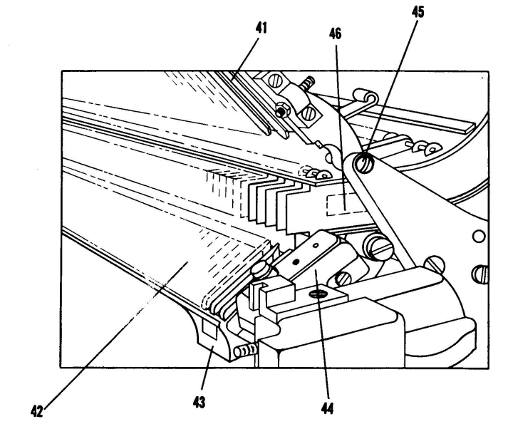
Fig. 5 View of Movable Channel Entrance Plates in Open Position.
The lower movable plate (42) is supported in position by a spring and linkage arrangement which also serves to return the plate to operating position once it has been deflected.
-12-
The lower movable section consists of two parts, the grooved plate, and an aluminum frame to which the grooved plate is attached. The aluminum frame is hinged from the channel entrance casting.
Horizontal Adjustment of Channel Entrance Upper and Lower Grooved Plate
A horizontal adjustment is provided for both upper and lower movable plates.
The lower plate can be shifted for horizontal positioning by loosening the 14 screws which fasten the lower grooved plate to the aluminum frame.
The upper movable grooved plate hinge screws (45 Fig. 5) are adjustable to provide for horizontal positioning of the upper plate.
The upper movable plate grooves, the lower movable plate grooves, and the partitions, must all be in proper alignment in order for matrices to pass through* the channel entrance freely. The partition plates with the partitions, the upper movable plate and lower movable plate can be horizontally adjusted independent of each other.
Vertical Adjustment of Channel Entrance
The channel entrance hinge pin adjustable bearings are for the purpose of vertically positioning the channel entrance in proper relation to the upper end of the magazines.
Flexible Partition Guides
Each partition of both channel entrances is equipped with a flexible guide (46, Fig. 5) attached for the purpose of preventing the thinner matrices from tilting and catching in the channel entrance.
The flexible guides should be very carefully shaped to support the thinner matrices, and at the same time deflect sufficiently for the thicker matrices to pass through the channel entrance. A special flexible guide shaper
-13-
1-8933 is recommended for the purpose of adjusting the guides properly and to avoid distorting them.
The flexible guides are readily accessible for proper and easy adjustment.
The large channel entrance of the wide range mixer models is equipped with a hinged section in the upper plate, and a section of the upper plate in the small channel entrance is easily removed by unhooking two small springs.
See Linotype Service Instructions No. 1 to No. 6 covering Models 29,
30, 33, 34, 35 and 36 respectively, for details concerning the operation and adjustment of the Electromatic Safety.
DISTRIBUTOR BOXES
The following material covers the Distributor Boxes on Mixer Models 29, 30, 35 and 36.
Upper Distributor Box
The matrix lift (26 Fig. 6) is adjusted by means of adjusting screw (27) so that the upper matrix lugs clear the vertical shoulders of the distributor box rails when the matrices are lifted. This adjustment is similar to that of single distributor models.

Fig. 6 Back View of Upper Distributor Box.
-14-
The matrix lift is flat at the top and is adjusted so that it will engage no more than one thin matrix at a time when the matrices are being lifted. This adjustment is accomplished by loosening screws (24) and adjusting the horizontal position of the separating block (25) which the lift bears against, by means of the adjusting screw provided.
Lower Distributor Box
To function properly, the lower distributor box must be kept clean, particularly the inside surface of the separating block (30) and the edges of the rails (28) and (29) Fig. 7. The matrices pass down over these rails by gravity, and grime or oil will retard their movement.
The matrix pusher (34 Fig. 7) is actuated by an end cam (35) and it must slide freely in the bearings. If it is sluggish, clean the rod, and oil lightly. Do not tighten the return spring (37). If the tension of this spring is excessive it will cause an uneven rotation of the distributor screws and undue wear on the distributor screw gears.
If there is side play in the matrix lift lever (32 Fig. 7), it can be taken up with the adjusting screws (33). These screws have pointed ends and should be adjusted evenly so as not to cause a side bind in the matrix lift (31).
The matrix lift (31 Fig. 8) is actuated by the cam (36) and should lift the matrices so that the upper lugs pass freely over the distributor box rails. The adjustment is made with adjusting screw (38).
The matrix lift is flat at the top and adjusted so that it will not engage more than one thin matrix at a time. When making this adjustment, place two thin matrices in the box and adjust nuts (39 Fig. 8) so that the lift does not engage the second matrix. When the adjustment is made, tighten the locknut. A special wrench G-3157 is required for this adjustment.
-15-
Fig. 7 Front View of Lower Distributor Box.
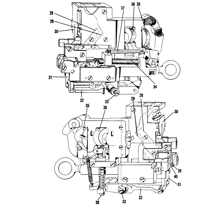
Fig. 8 Back View of Lower Distributor Box.
-16-
Timing the Distributor Boxes
The upper and lower sections of the distributor are timed relatively, so that the matrix pusher of the lower box is in the open position to receive a matrix as it completes its descent from upper box. This timing is accomplished in the following manner: Remove the distributor driving belt, then disconnect the intermediate idler gear (54 Fig. 9) by removing the stud. This will leave the distributor sections independent of each other.
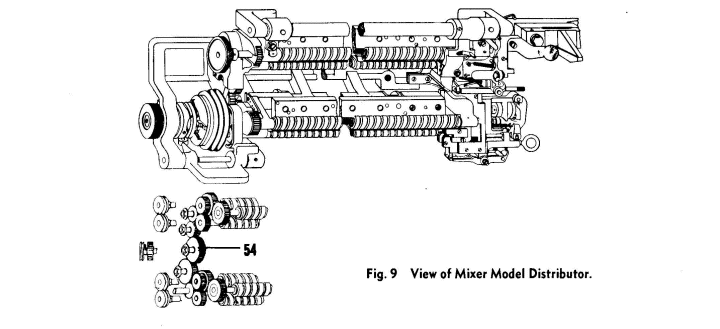
Fig. 9 View of Mixer Model Distributor
Turn the lower section by hand in its regular direction until the matrix pusher (34 Fig. 7) travels forward to its limit, and then moves in the opposite direction until its prongs are approximately 1/8" from the shoulders of the distributor box rails. Allow it to remain in this position. Slide a matrix, which is properly bridge notched, through the upper distributor box and then turn the upper section of the distributor very slowly and observe the matrix. At the instant it drops from the upper distributor box into the chute, stop turning and reconnect the two distributor sections with the intermediate idler gear (54 Fig. 9). The timing of the two distributor boxes will then be correct.